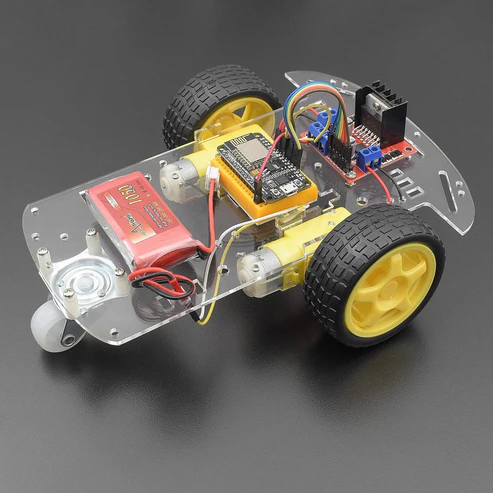
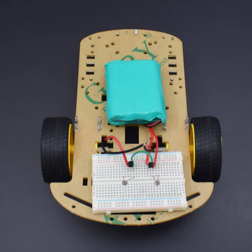
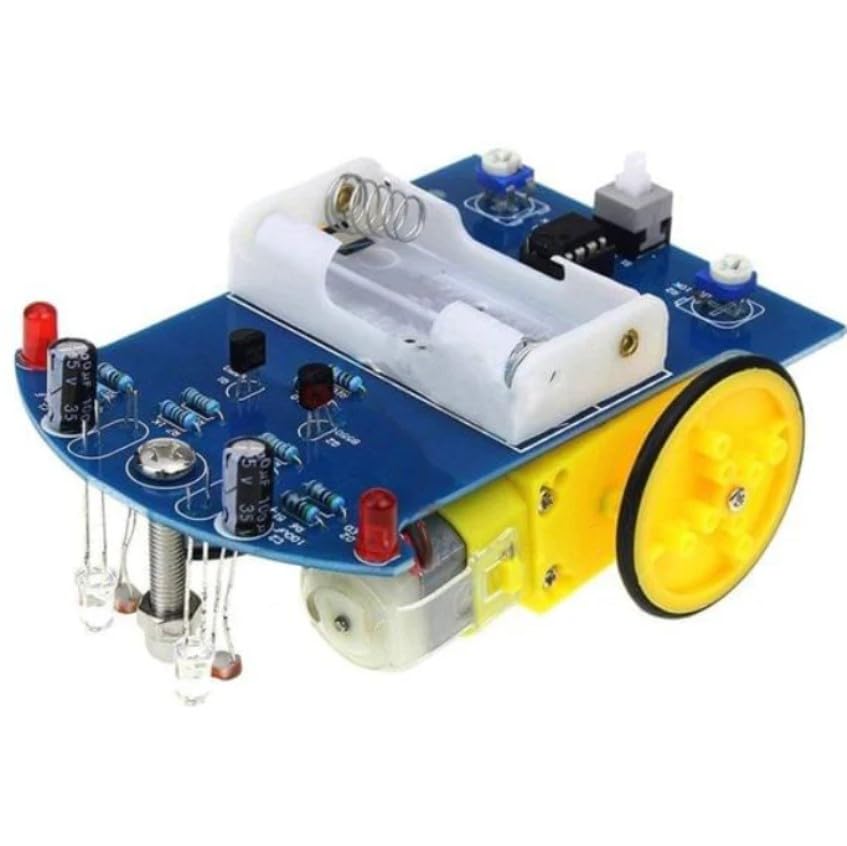
Make a Radio Car using 434 MHz RF Link Transmitter receiver kit
$77.61
$146.68
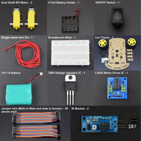
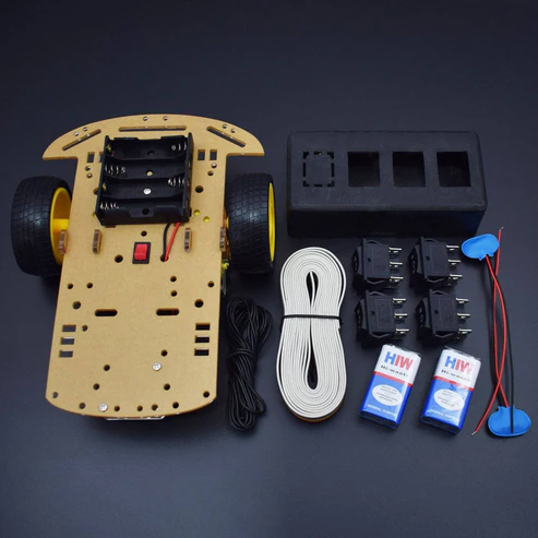
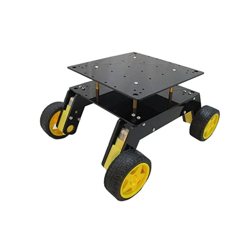
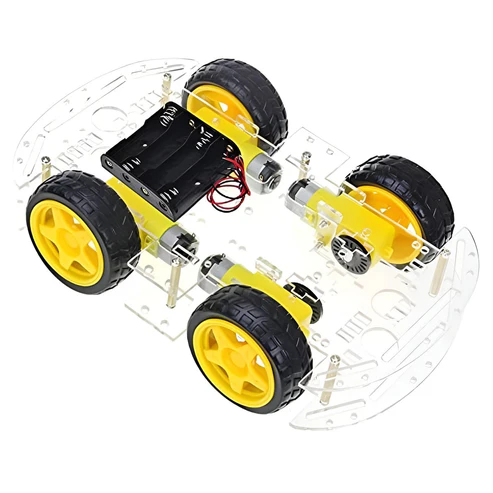
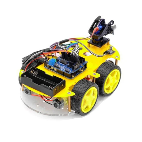
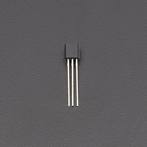
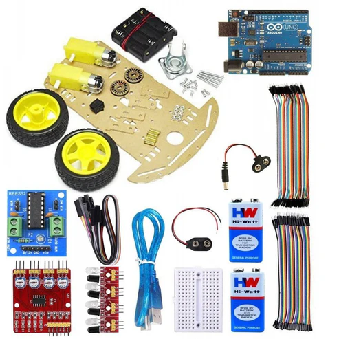
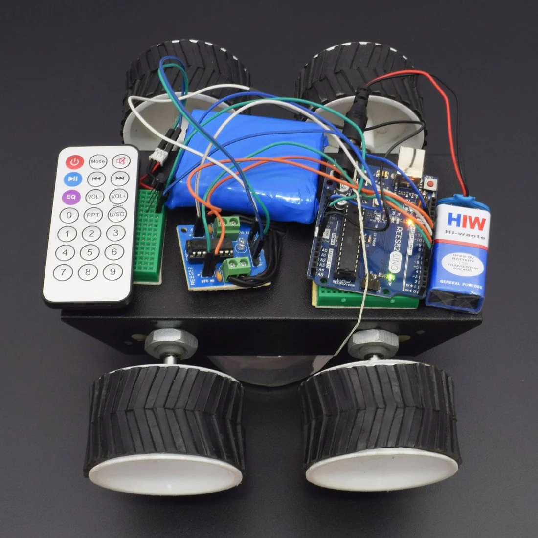
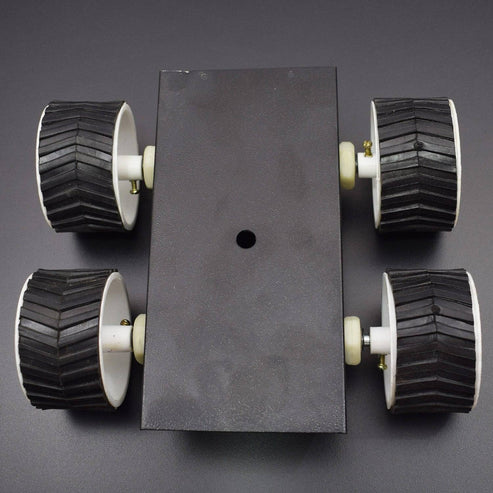
434 MHz RF Link Transmitter receiver kit Frequency 434 MHz Transmitter supply voltage: 3~12V. Receiver Supply voltage: 5V Receiver IF frequency: 500 kHz Receiver Sensitivity: -105dBm Receiver Supply current: 2.3mA Output power: 4~16dBm Operating Voltage: 5 Volts HARDWARE REQUIRED 1x Voltage Regulator 7805 2x 1N4001 Diode 1x HT12E Encoder 1x HT12D Decoder 1 x 434MHz RF Link Transmitter Receiver kit 2x 1K Resistor 2x 3.3K Resistor 2x 47K Resistor 2x 1M Resistor 1X L293D Motor Driver IC 2x Electrolytic Cap 16V 100uF 4x 5mm LED 2x DPDT Rocker switch 1x 9V Battery Clip 1x 9V Battery 1x Plastic Enclosure 1x Robot 3-wheel Chassis kit 1x SPST Rocker Switch 1x Hook-Up Wires AWG22 Solid 1x 12V lithium-ion battery 1x breadboard (400pins) 1Xbreadboard (800 pins) SPECIFICATIONS 434 Mhz Transmitter Reciever Kit Frequency 434 MHz Transmitter: Saw filter based ASK hybrid transmitter Transmitter supply voltage: 3~12V.R receiver: ASK superheterodyne receiver with PLL synthesizer and crystal oscillator. Receiver Supply voltage: 5V Receiver IF frequency: 500 kHz Receiver Sensitivity: -105dBm Receiver Supply current: 2.3mA Output power: 4~16dBm Turn on time: 20mS from power is switched on. Data rate 200bps to 3Kbps depending on the supply. Operating voltage: 5 Volts PIN DESCRIPTION Voltage Regulator 7805 Led Electrolytic Capacitor L293DE Motor Driver IC HT12D Decoder IC HT12E Encoder IC 434 Mhz Transmitter Receiver Kit Transmitter PCB Layout Receiver PCB layout HOW TO MAKE REMOTE Cut the Parts as given in picture above: Remote will be shown like this Connection made as given in picture above for DPDT Switch CIRCUIT CONNECTION Switch Connection Transmitter (Remote Controller) connection Connect Pin 1 to 9 and pin 14 to the ground of HT12E IC Connect pin 16 and 15 via 1M resistor of HT12E IC Connect Pin 17 of HT12E to data pin of RF link transmitter and pin 18 to the 5v ( Positive rail on breadboard ) Connect pins 10,11,12,13 to the DPDT Rocker switch (s2 and s3 as shown in the photo. Connect Pin 1 of RF link transmitter to GROUND and pin 3 (VCC) to 5v and connect antenna to pin 4. Connect the ground pin of 7805 voltage regulator to the ground ,Vin to switch s1 one point and other point to 9v battery then c1(100uf)’s positive Vin and negative to ground and then Vo to Positive rail and c2 capacitor. Positive to Vo and negative to gnd. 1k resistor one terminal to ground and other terminal to negative of led and positive of led to the positive rail. Receiver (RC car) Connection Place the decoder IC(HT12D) the motor driver IC and the RF link receiver to the breadboard Connect the 1 to 9 pins of decoder IC to the ground Pin ten of ht12d goes to pin 2 of L293d, pin 11 goes to pin 7, pin 12 goes to pin 10 and pin 13 goes to pin 15. Pin 14 of ht12d goes to pin 2(data) of RF link receiver. Pin 15 is connected to pin 16 of HT12D via 50k resistor. Pin 17 is connected to 1k resistor one terminal and other terminal of resistor to the -ve of led and the positive of led to the 5v rail of breadboard. Pin 18 is also goes to 5v rail. Pin no. 1,8,9,16 of L293D goes to the 5v rail. Pin no. 4,5,12,13 to the ground. Pin 3 and 6 connected to motor m1 and pin no. 11 and 14 to the motor m2. All three ground pins in the RF link receiver goes to GND rail,vcc1 and vc2 to 5v rail and antenna is connected to Pin 8(ant). Now connect one 1N4001 Diode to breadboard connect Positive of diode to the one point of SPST Rocker Switch and other point of Switch to the 12v li ion battery positive point. Negative point of diode to the positive rail. If you want to make this RC car on PCB: