$33.12
$63.26
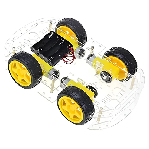
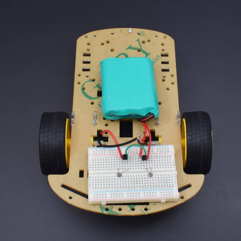
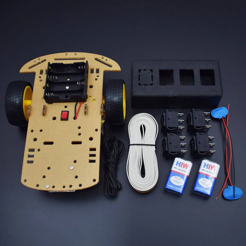
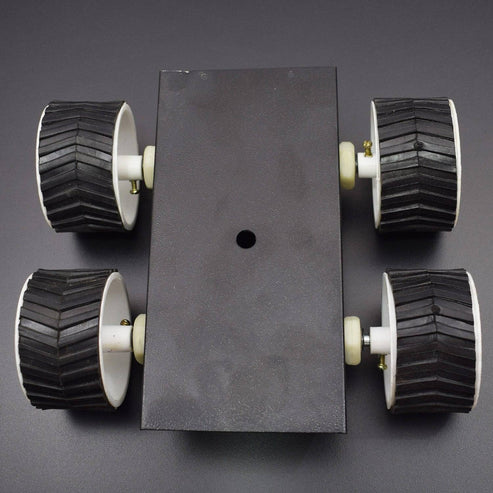
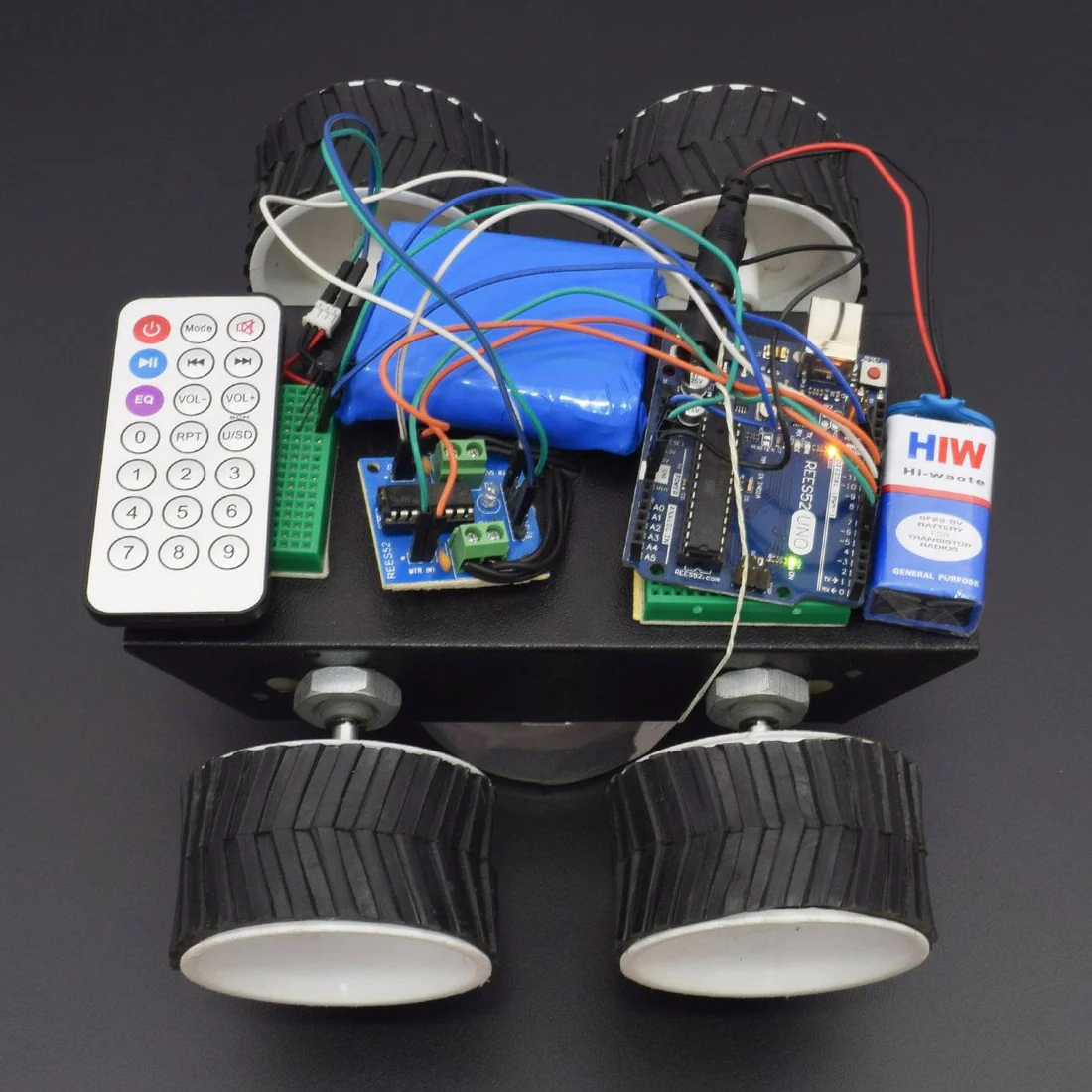
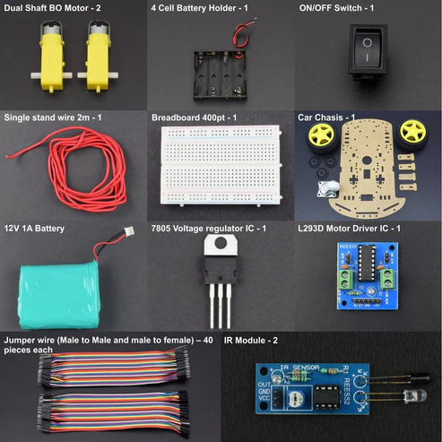
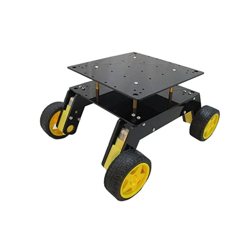
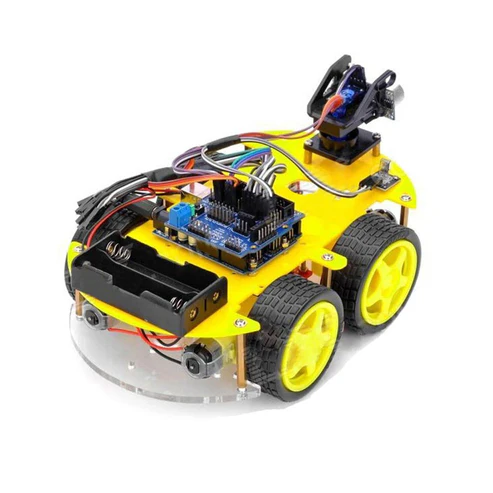
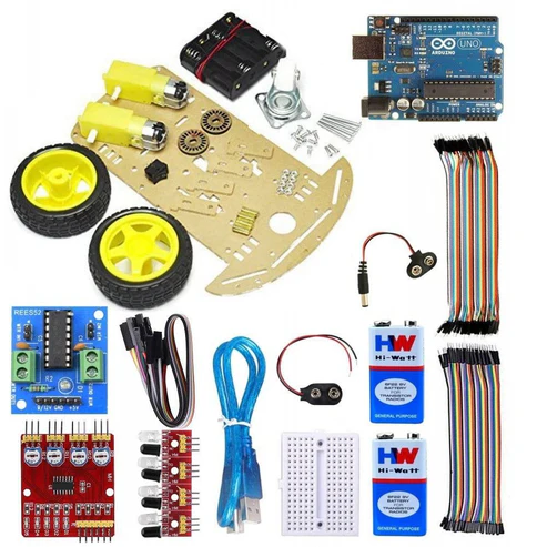
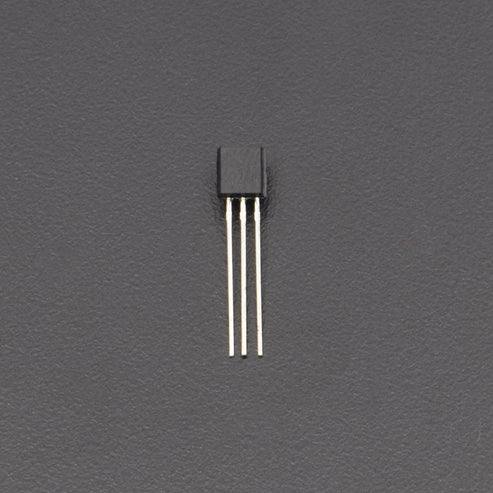
KIT INCLUDES: HARDWARE REQUIRED Arduino Uno and USB cable – 1 200rpm DC Gear Motor – 4 TSOP – 1 L293D motor driver module – 1 Jumper wire male to male – 40 pieces Jumper wire male to female – 40 pieces 7*4 Robotic wheel – 4 9V battery with DC jack – 1 Breadboard 170 points – 1 12v Lithium Ion Battery – 1 4 Wheel Black chassis 1 IR Remote controller – 1 SOFTWARE REQUIRED Arduino IDE 1.8.5 (programmable platform for Arduino) Click To Download :https://www.arduino.cc/en/Main/Software CIRCUIT CONNECTION Fix the wheels to the chassis. Attach the 2 motors to the back wheels and use dummies for the front. Make holes on the chassis and fix Arduino using screws. Fix the breadboard by using the double sided tape provided on it. Mount the L293D on the breadboard with the notch facing front. IR Receiver Connections Facing the notch on the receiver, the connections from left to right are left pin-ground. middle pin-5V. right pin-digital pin 6 on Arduino. Saving the IR Library Go to the following link- https://drive.google.com/open?id=0B621iZr0p0N_WUVmbW5kRFIxaVU Save the files within a folder named IR remote and save the folder in the libraries directory of your Arduino IDE i.e. arduino-1.0.6>libraries folder as IR remote. Finding Hexadecimal Values of Remote Keys 1. Upload the code in remote.ino into the Arduino 2. Open the serial monitor. 3. Press different remote keys and obtain their hexadecimal values.(Note that the values will not be obtained with 0x which represents hexadecimal also some values are obtained in middle like FFFFFFFF, ignore them). Here I have obtained the values of the front, back,left,right and middle keys which are front= 0x80BF53AC back= 0x80BF4BB4 left= 0x80BF9966 right= 0x80BF837C middle= 0x80BF738C These values of these buttons are mapped to move front,move back,move left,move right and brake respectively. Take 5V and ground from Arduino and connect them to the 2 bottom rails of breadboard, thus giving a 5V and ground line. Pins 1,9,16 from L293D to 5V. Pins 4,5,12,13 from L293D to ground. Left motor to pins 3,6 on L293D. Right motor to pins 11,14 on L293D. Pins 2,7(for left motor)from L293D to pins 9,8 on Arduino. Pins 10,15(for right motor)from L293D to 10,11 pins on Arduino. Refer to schematics for more details. Note that in the schematic yellow wires represent left motor and orange wires right motor. Interfacing Motors with L293D After making the connections, upload the code in motor_test.ino into the Arduino. Note that for left motor to rotate, lm,lmr should be opposite i.e HIGH and LOW or vice versa. . Similarly for right motor to rotate, rm,rmr should be opposite i.e HIGH and LOW or vice versa. Determine the logic levels of lm,lmr,rm,rmr for both the wheels to go forward by trial and error. For me it was LOW,HIGH,HIGH,LOW. Thus the inputs required to go forward are LOW,HIGH,HIGH,LOW. Inputs required to go backward are HIGH,LOW,LOW,HIGH. Inputs required to go right are LOW,HIGH,HIGH,HIGH(i.e. only left motor should rotate). Inputs required to go left are HIGH,HIGH,HIGH,LOW(i.e. only right motor should rotate). Note that values of lm,lmr,rm,rmr obtained may be different from above. Integrating Everything Now integrate everything i.e. both the ir receiver part and L293D part. The schematic given above is just a combination of schematics of IR receiver and L293D. Basically you can first make the IR connections, find hexadecimal value and without disturbing the IR connections, make the L293D connections and interface the motors with Arduino. Step 9: Power Supply 9V powering the Arduino with positive of battery given to vin pin of Arduino and negative given to the second ground pin of Arduino 9V for Vss supply(pin 8) of l293d which is used for driving the motors(max value that can be given is 36V) Step 10: Final Program Upload the code given in rc_car.ino into the Arduino (provided both IR and L293D connections have been made). The code just like the previous schematic is just an integration of remote and motor test codes i.e. the Arduino first now checks the remote key which you have pressed by obtaining its hexadecimal value ,checks what function has been mapped to that value and performs the required function through L293D Check if the bot moves as required or not. Go to this repository to download the code and schematics. Click on the “Clone or Download” button (green in color on the right side) and select “Download ZIP” to download the zip file. Now extract the contents on your computer to get the code and schematics (in the schematics folder). Important instructions regarding the ir remote control robot During motor connections you may quiet watch the connections of motors and check the proper direction of the motors in which the motor rotate so it is easy to rotate your robot. You may also use the l293d motor driver module it is easy to use and connections and use two batteries 1 12v for motors and 9v for arduino uno. And you will easily access the robot and you may also change some codes of motors that in which direction you may connect you will see and change the changes in codes. CODE https://docs.google.com/document/d/e/2PACX1vThTFmdLrLsouwnwe0qzx1sBHIvhoUhOevhYDfjp24mVH46Rk5vCVeqKCIMmn7NAzElTiWj5swK998v/pub #include <IRremote.h> // Library for IR Remote int lm=4; // Digital Pin 4 for the IN1 of L293D Motor Driver Module int lmr=5; // Digital Pin 5 for the MTR of L293D Motor Driver Module int rm=6; // Digital Pin 6 for the MTR of L293D Motor Driver Module int rmr=7; // Digital Pin 7 for the IN2 of L293D Motor Driver Module int RECV_PIN = 11; // Digital Pin 11 for the IR Receiver IRrecv irrecv(RECV_PIN); decode_results results; /* The setup() function is called when a sketch starts. It is used to initialize variables, pin modes, start using libraries, etc. This function will only run once, after each power up or reset of the Arduino board. */ void setup() { pinMode(lm,OUTPUT); // Pin 4 acts as Output Pin pinMode(lmr,OUTPUT); // Pin 5 acts as Output Pin pinMode(rm,OUTPUT); // Pin 6 acts as Output Pin pinMode(rmr,OUTPUT); // Pin 7 acts as Output Pin Serial.begin(9600); // Baud Rate irrecv.enableIRIn(); // Start the receiver } /* This Particular Function is used for Repeated Execution of the Circuit until Specified. */ void loop() { if (irrecv.decode(&results)) { Serial.println(results.value, HEX); // Print the values irrecv.resume(); // Receive the next value } if(results.value==0xFF18E7) // Forward Direction { digitalWrite(lm,LOW); // Pin 4 is active digitalWrite(lmr,HIGH); // Pin 5 is inactive digitalWrite(rm,LOW); // Pin 6 is active digitalWrite(rmr,HIGH); // Pin 7 is inactive } if(results.value==0xFF4AB5) // Backward Direction { digitalWrite(lm,HIGH); // Pin 4 is inactive digitalWrite(lmr,LOW); // Pin 5 is active digitalWrite(rm,HIGH); // Pin 6 is inactive digitalWrite(rmr,LOW); // Pin 7 is active } if(results.value==0xFF10EF) // Left Direction { digitalWrite(lm,LOW); // Pin 4 is active digitalWrite(lmr,HIGH); // Pin 5 is inactive digitalWrite(rm,HIGH); // Pin 6 is inactive digitalWrite(rmr,LOW); // Pin 7 is active } if(results.value==0xFF5AA5) // Right Movement { digitalWrite(lm,HIGH); // Pin 4 is inactive digitalWrite(lmr,LOW); // Pin 5 is active digitalWrite(rm,LOW); // Pin 6 is active digitalWrite(rmr,HIGH); // Pin 7 is inactive } if(results.value==0xFF38C7) // To stop the Car { digitalWrite(lm,HIGH); // Pin 4 is inactive digitalWrite(lmr,HIGH); // Pin 5 is inactive digitalWrite(rm,HIGH); // Pin 6 is inactive digitalWrite(rmr,HIGH); // Pin 7 is inactive } } WORKING This is an interactive project in which we are making an IR control Robot using IR remote interfacing with Arduino uno. This remote controlled car can be moved around using practically any kind of remote such as TV, AC etc. It makes use of the fact that the remote emits IR (infrared).
Robot Car Kits & Accessories