Access a 4 digit Passcode using joystick module and display the code on 16*2 Lcd interfacing with Arduino uno
$50.95
$87.63
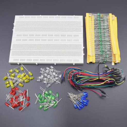
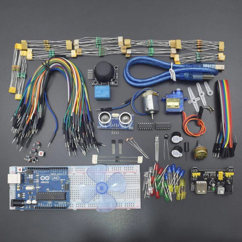
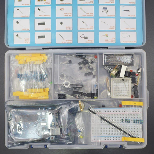
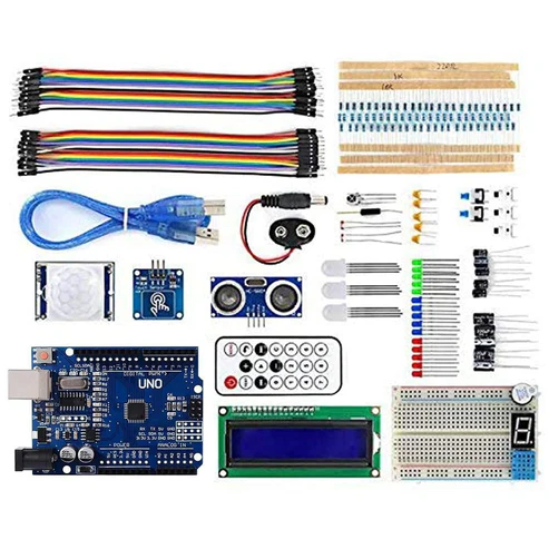
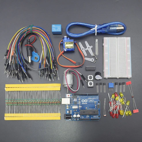
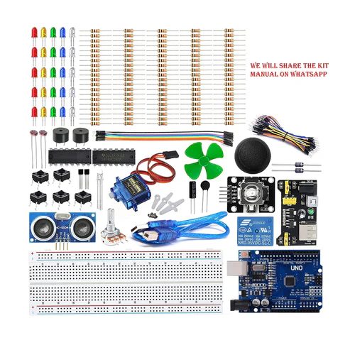
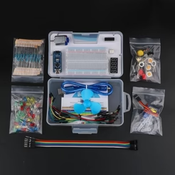
KIT INCLUDES: Arduino Uno with USB cable – 1 Breadboard 830 points – 1 Potentiometer 10k – 1 16*2 LCD Display – 1 Joystick module – 1 Jumper wires male to male – 40 pieces Jumper wires male to female – 40 pieces Resistor 820 OHM – 5 Introduction In this project, we will make a 4 digit passcode safe lock using the Ps2 joystick module and 16*2 Lcd display. We will move the joystick in x and y direction to increase or decrease the value from 0 to 9 and other to move the joystick in up and downside to move the cursor in both left and right direction which is displayed on the display. HARDWARE REQUIRED Arduino UNO with USB cable – 1 Breadboard 830 points – 1 Potentiometer 10k – 1 16*2 LCD Display – 1 Joystick module – 1 Jumper wires male to male – 40 pieces Jumper wires male to female – 40 pieces Resistor 820 OHM – 5 SOFTWARE REQUIRED Arduino IDE 1.8.5 (programmable platform for Arduino) Click To Download:https://www.arduino.cc/en/Main/Software SPECIFICATIONS Joystick Module Supply Voltage: 3.3V to 5V Interface: Analog x2,Digital x1 PH2.0 Interface Size:35x39mm Weight:15g 16*2 LCD Standard 16×2 Character LCD 16 Characters Wide x 2 Lines 5 x 8 Dots with Cursor Built in Controller (HD44780 or equivalent) 3.3V Power Supply Backlight Included PIN DESCRIPTION Joystick module 10k potentiometer 16*2 LCD Display CIRCUIT DESCRIPTION NOTE – here we are using a 10k potentiometer but as shown in the figure, the resistor going from 5v and GND to the LCD pin3 V0 replace the 10K potentiometer. You can use 1k ohm from 5v and 330 ohms going down to GND but you may use different resistors or pot depending on the LCD, But for the convenience, we are using 10K pot. Joystick Module – Arduino Uno Joystick module has 5 pins gnd, vcc,vrx,vry,sw NOTE – Here this switch pin on Joystick must be connected to a digital output pin mode. if not then it doesn’t give accurate readings so best to use digital pin 13 here. Joystick Module Arduino Uno Vcc 5v Gnd Gnd VRx A1 VRy A0 SW 13 16*2 LCD Display – Arduino Uno 16*2 LCD Dsiplay Arduino uno VSS Gnd VDD 5v V0 Middle(Data) pin of 10k potentiometer RS 12 R/W Gnd E 11 D4 5 D5 4 D6 3 D7 2 A VCC via 820 ohm K GND CODE Click to see the code or copy the link https://docs.google.com/document/d/e/2PACX-1vTn_pB0Uge7h7z1bjZBaeOYeHJjFdMH2PJ9EduJs1K7t2dVS7qC87mmCjCImVtW2EpriGhAsLLnWErk/pubhttps://goo.gl/b555XC WORKING Plug the supply to Arduino UNO after uploading the code you see the text on display enter the code Now you enter the code using the joystick movement left to right to change the cursor position Move the joystick Down and up to change the number. Now set the number as mentioned in the code (you can change in the code ). Now press joystick after taking in the center position so you can see the REES52 Lock on (You can customize it) password on the LCD display.